Introduction Last updated: 2023-06-01

  • supported modules
  • ESP32
  • ESP32-S3
  • ESP32-C3
  • ESP8266
  • ESP8285-SOON

  • Update Info:
  • Update in:fast boot-ds sensor-serial-auto start config
  • Update title:fast boot-ds sensor-serial-auto start config

Download KME Tools: V24


If there are any problems uploading the frame, please upload them using (Esp tools)

Connect To Device


Select Port:

Choose the communication port your device is connected to.

Connect to COM Port:

Establish a connection with the selected COM port to upload widgets and firmware.

Upload Firmware:

Transfer the firmware to the device for installation.

Refresh to View Device ID:

Refresh the page to display the device ID once the upload is complete.
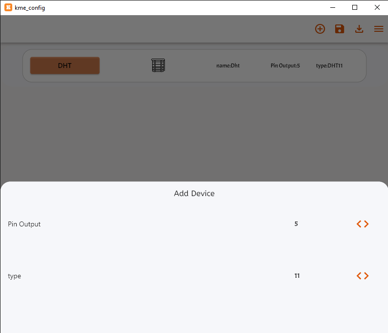
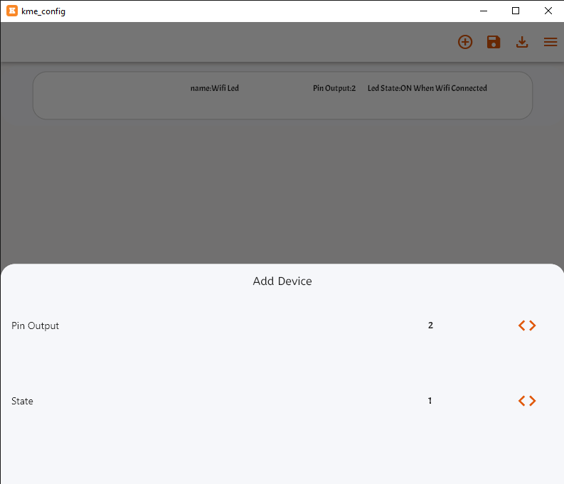
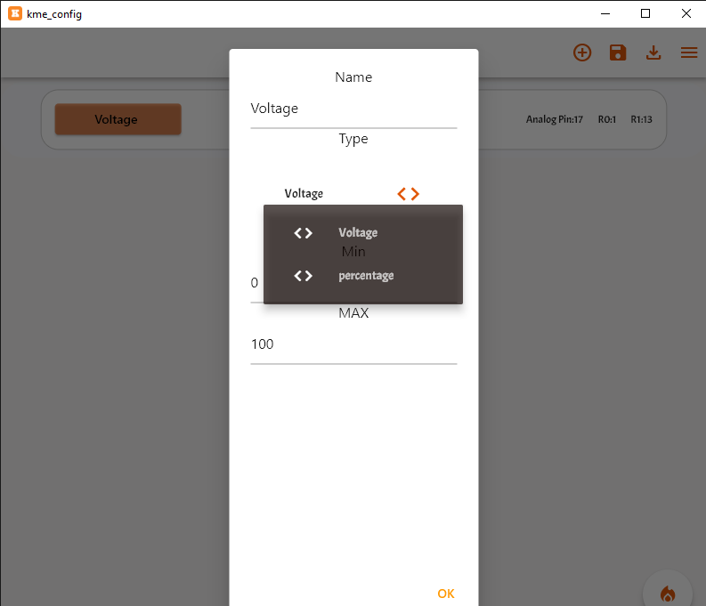

Add element


Step 1:

Press the plus icon to add an element.

Step 2:

Press the plus icon to add an element.

Step 3:

Edit the necessary pin IDs.


Upload widget


DHT

DHT Configuration.

  • DHT supported types
  • DHT11
  • DHT21
  • DHT22


Step 1:

Add DHT Sensor.

Step 2:

Edit the pins if You need.

  • DHT configuration description
  • PIN Out:Select "DHT Humidity Sensor" GPIO .
  • TYPE: Select "DHT Humidity Sensor" Type .


Contact

Contact Configuration.

Digital Input Sensor: A digital input sensor is a sensor that provides binary output signals, typically representing "on" or "off" states. These sensors are often used to detect the presence or absence of an object or to monitor the status of a switch or button.


Step 1:

Add Contact Sensor.

Step 2:

Edit the pins if You need.

  • Contact configuration description
  • PIN Out:Select "Contact Sensor" GPIO .
  • PULL UP OR DOWN FOR INPUT: Select 'Contact Sensor' for input pull-up or pull-down.


Relay configuration

Relay: A relay is an electromechanical switch used to control high-power electrical devices by using low-power electrical signals. It allows you to control circuits with a microcontroller or other low-power signal.


Step 1:

Add relay Output.

Step 2:

Edit the pins if You need.

  • relay configuration description
  • HIGH OR LOW:Select "relay mode" Active_Low or Active_High .
  • PIN Out:Select "relay" GPIO .
  • PULL UP OR DOWN FOR INPUT: Select 'INPUT Pull Type' for input pull-up or pull-down.
  • INPUT: Select 'INPUT' to control relay by switch
  • S||P: Select 'INPUT' for Switch or Push Button.


RGB Configuration

The RGB WS2812B strip is a programmable LED strip that features individually addressable RGB LEDs, allowing for dynamic and colorful lighting effects. Each LED on the strip can be controlled independently, enabling a wide range of lighting patterns and animations. It's commonly used in various projects such as ambient lighting, decorative displays, and visualizations, offering vibrant and customizable illumination.


Step 1:

Add RGB Output.

Step 2:

Edit the pins if You need.

  • RGB configuration description
  • PIN Out:Select "RGB" GPIO .
  • PULL UP OR DOWN FOR INPUT: Select 'INPUT Pull Type' for input pull-up or pull-down.
  • INPUT: Select 'INPUT' to control RGB by switch.
  • S||P: Select 'INPUT' for Switch or Push Button.


Dimmer Configuration

The duty cycle refers to the percentage of time that a signal is active or on within a given period. In other words, it represents the proportion of time that a signal spends in its high state compared to its total period. Duty cycles are commonly used to control the average power delivered to a load in applications such as pulse-width modulation (PWM), where varying the duty cycle alters the perceived brightness, speed, or intensity of an output.


Step 1:

Add Dimmer Output.

Step 2:

Edit the pins if You need.

  • Dimmer configuration description
  • PIN Out:Select "Dimmer" GPIO .
  • PULL UP OR DOWN FOR INPUT: Select 'INPUT Pull Type' for input pull-up or pull-down.
  • INPUT: Select 'INPUT' to control Dimmer by switch.
  • S||P: Select 'INPUT' for Switch or Push Button.


Remote

Remote Configuration.

  • supported Remotes for control (relays,rgb,dimmers)
  • IR
  • RF433


Step 1:

Add Remote Sensor.

Step 2:

Edit the pins if You need.

  • Remote configuration description
  • PIN Out:Select "Remote" GPIO .
  • type:Select "type" [ir,rf433] .


Wi-Fi LED

Wi-Fi LED Configuration.

Wi-Fi Status Led


Step 1:

Add Wi-Fi LED .

Step 2:

Edit the pins if You need.

  • Wi-Fi LED configuration description
  • PIN Out:Select "Wi-Fi LED" GPIO .
  • Led State:Select "Wi-Fi LED" State if Connected .


Pairing Button

Pairing Button Configuration.

The Pairing Button facilitates connecting the device to Wi-Fi networks. Pressing the button initiates the pairing process, enabling seamless Wi-Fi configuration without the need for complex setup procedures."


Step 1:

Add Pairing Button.

Step 2:

Edit the pins if You need.

  • Pairing Button configuration description
  • PIN Out:Select "Pairing Button" GPIO .
  • PULL UP OR DOWN FOR INPUT: Select 'pairing button' for input pull-up or pull-down.


Analog Sensor

Analog Sensor configuration.

  • Analog Sensor types
  • voltage:It reads the voltage via the divider .
  • percentage:It converts the voltage value into a percentage.


Step 1:

Add Analog Sensor Sensor.

Step 2:

Edit the pins if You need.

  • Analog Sensor "Voltage" configuration description
  • PIN Out:Select "Analog Sensor" GPIO .
  • R2:Select resistor value for divider .
  • R1:Select resistor value for divider .

  • Analog Sensor "percentage" configuration description
  • PIN Out:Select "Analog Sensor" GPIO .


IR Hub

IR Hub configuration.


Step 1:

Add IR Hub.

Step 2:

Edit the pins if You need.

  • IR Hub configuration description
  • Receiver Pin " Receiver ir " GPIO.
  • Transmitter Pin " Transmitter IR led" GPIO.


Fan

Fan configuration.


Step 1:

Add Fan.

Step 2:

Edit the pins if You need.

  • Fan configuration description
  • PIN Out:Select "Analog Sensor" GPIO .
  • R2:Select resistor value for divider .
  • R1:Select resistor value for divider .

  • Analog Sensor "percentage" configuration description
  • PIN Out:Select "Analog Sensor" GPIO .


KMESerial Library Code Description

This Library controls GPIO pins based on switch states received from the KMESerial library and updates sensor values periodically. It also handles time synchronization based on information received from KMESerial.


Main Features:

  • 1. Switch State Handling: Manages multiple switch states, assigning them to corresponding GPIO pins and controlling the pin's output based on the switch state (ON/OFF).
  • 2. Sensor Updates: Periodically updates sensor values and sends them to KMESerial.
  • 3. Time Synchronization: Synchronizes the system time based on data received from KMESerial and displays it in a formatted way.

Functions Description:

1. switchstate(KME State)

This function is a callback that handles changes in switch states. It checks the State.id of the switch and maps it to a corresponding GPIO pin. Based on the switch state (ON or OFF), it sets the GPIO pin output to HIGH or LOW. Additionally, the switch state is updated using KMESerial.SetSwitch.

  • Parameters: State object that contains id and value for the switch.
  • Actions: Maps the id to a specific GPIO and controls its output accordingly.

2. setup()

The setup() function runs once when the microcontroller starts. It initializes the GPIO pins as outputs, sets up serial communication at a baud rate of 74880, and retrieves the status of the switches using KMESerial.getStatus(). It also sets up the callback function to handle switch state changes.

  • Actions: Initializes serial communication, sets GPIO pins as outputs, retrieves switch status, and configures the KMESerial callback.

3. loop()

The loop() function continuously runs after the setup is completed. It periodically updates sensor values, manages KMESerial communication, and handles time synchronization when the conditions are met. It also prints the current time and heartbeat value from KMESerial.

  • Actions: Updates sensor values, checks for heartbeat changes, and synchronizes time based on KMESerial data.

Library for GPIO Control and Sensor Updates

This Library controls GPIO pins based on switch states received from the KMESerial library and periodically updates sensor values. It also synchronizes time based on information from KMESerial.

Example Usage

void switchstate(KME State) {
  byte gpio = 0;
  // Check for each switch ID and assign corresponding GPIO pin
  if (State.id == 0) {
    gpio = 13;
  } else if (State.id == 1) {
    gpio = 8;
  } else if (State.id == 2) {
    gpio = 7;
  } else if (State.id == 3) {  // New switch with ID 3
    gpio = 12;
  }

  // Control the corresponding GPIO based on the switch state
  if (State.value == 1) {
    digitalWrite(gpio, HIGH);  // Turn ON the GPIO pin
  } else {
    digitalWrite(gpio, LOW);   // Turn OFF the GPIO pin
  }

  // Send updated switch state back to KMESerial
  KMESerial.setSwitch(State.id, State.value);
}

void setup() {
  Serial.begin(74880); 
  pinMode(13, OUTPUT);  // GPIO pin 13
  pinMode(8, OUTPUT);   // GPIO pin 8
  pinMode(7, OUTPUT);   // GPIO pin 7
  pinMode(12, OUTPUT);  // GPIO pin 12 (new switch)

  KMESerial.getStatus(0);
  KMESerial.getStatus(1);
  KMESerial.getStatus(2);
  KMESerial.getStatus(3);
  
  KMESerial.setCallback(switchstate);
  KMESerial.getSettings(0);
}

void loop() {
  val += 20;
  secondSensorVal += 10;
  
  KMESerial.loop();
  delay(300);
  
  KMESerial.setSensor(0, val);
  KMESerial.setSensor(1, secondSensorVal);
  
  if (heartbeat != KMESerial.info().heartbeat) {
    Serial.print("heartbeat:");
    Serial.print(KMESerial.info().heartbeat);
    heartbeat = KMESerial.info().heartbeat;
  }
  
  if (timegeted && val > 100) {
    timegeted = false;
    Serial.print("info:");
    Serial.println(KMESerial.info().currentTime);
    
    setTime(KMESerial.info().currentTime);
    Serial.print("Current Time: ");
    Serial.println(now());
    
    Serial.print("Formatted Time: ");
    Serial.print(hour());
    Serial.print(":");
    Serial.print(minute());
    Serial.print(":");
    Serial.print(second());
    Serial.print(" ");
    Serial.print(day());
    Serial.print("/");
    Serial.print(month());
    Serial.print("/");
    Serial.println(year());
  }
}

Functions

switchstate(KME State)

This function is a callback that handles changes in switch states. Based on the State.id, it maps to a corresponding GPIO pin. When the switch is turned ON or OFF, the function updates the GPIO pin output to HIGH or LOW and sends the updated switch state back through the KMESerial library.

Parameters:

  • State: A KME object that contains the id and value of the switch.

The function controls the following GPIO pins based on the switch id:

  • id == 0 -> GPIO 13
  • id == 1 -> GPIO 8
  • id == 2 -> GPIO 7
  • id == 3 -> GPIO 12 (new switch)

The GPIO pin is set to HIGH if State.value == 1, otherwise LOW.

setup()

This function is called once when the microcontroller starts. It initializes serial communication, sets GPIO pins as outputs, prepares communication through the KMESerial library, retrieves switch statuses, and sets up a callback to handle switch state changes.

Key Tasks:

  • Initializes serial communication with a baud rate of 74880.
  • Sets up GPIO pins 7, 8, 12, and 13 as output pins for controlling external components.
  • Retrieves initial switch statuses for IDs 0, 1, 2, and 3 using KMESerial.getStatus().
  • Sets up the switchstate() callback to handle switch state changes.
  • Retrieves settings for switch ID 0 using KMESerial.getSettings().

loop()

This function is called repeatedly after the setup() function and performs the following tasks:

Key Tasks:

  • Increments sensor values val by 20 and secondSensorVal by 10 on each iteration.
  • Updates sensor values for ID 0 and ID 1 using KMESerial.setSensor().
  • Executes the KMESerial.loop() function to handle communication with the KMESerial library.
  • Checks if the heartbeat value has changed and prints it if there is an update.
  • Performs time synchronization once val > 100 and prints the synchronized time in both raw and formatted formats.

Time Synchronization:

  • Once the condition val > 100 is met, the current time from KMESerial is retrieved and set using the setTime() function.
  • The current time is printed in both raw seconds and in a formatted hh:mm:ss dd/mm/yyyy format.

Variables

  • val: The main sensor value that is incremented by 20 in each loop iteration.
  • secondSensorVal: The second sensor value that is incremented by 10 in each loop iteration.
  • heartbeat: Tracks the heartbeat signal received from KMESerial. If the heartbeat changes, it prints the new value.
  • timegeted: A flag that ensures time synchronization only happens once when val > 100.

Notes

  • The Library controls four switches mapped to GPIO pins 7, 8, 12, and 13. Additional switches can be added by extending the switchstate() function.
  • The sensor values for ID 0 and 1 are updated periodically based on val and secondSensorVal.
  • The KMESerial library handles the communication and switch state changes, and is also used for time synchronization.

GitHub Code:

For detailed source code and documentation, refer to the KMESerial GitHub Repository.